CP5070-2022-2B03-GROUP1-ADYL BIN YANI


Gears
A gear is a circular machine part with teeth along the circumference. It is used to transfer torque and motion from a source of rotational energy such as a motor to other machine parts. Gears come in 3 categories - Driver, Idler and Follower. The driver is where the motor exerts torque onto the gear and the follower is the final gear in a 2-gear simple gear train whereby the driver and follower gears rotate in opposite directions to each other.. in a 3-gear gear train, the idler is the middle gear which allows the driver and follower gear to spin in the same direction. One more important thing to note is gear ratio. Gear ratio can be taken as the ratio of the number of teeth of the driven gear to the number of teeth of the driver gear. There are other ways to calculate gear ratio but this would be the main one.
In this blog, I will cover:
-
The definition of gear module, pitch circular diameter and the relationship between gear module, pitch circular diameter and number of teeth.
-
The relationship between gear ratio (speed ratio) and output speed, between gear ratio and torque for a pair of gears.
-
How I can design a better hand-squeezed fan, including the sketches
-
How my practical team arranged the gears provided in the practical to raise the water bottle, consisting of:
a. Calculation of Gear Ratio (Speed Ratio)
b. Photo of the actual gear layout
c. Calculation of the number of revolutions required to rotate the crank handle
d. The video of the turning of gears to lift the water bottle
5. My Learning reflection on the gears activities


These are the definition of gear module, pitch circular diameter and the relationship between gear module, pitch circular diameter and number of teeth:
1 / Gear Teeth
Gear teeth are the studs on a wheel that protrude out of the main wheel body.
2 / Gear Module
Gear module, denoted as "m" is defined as the unit of size of the gear tooth.
3 / Pitch Circular Diameter (PCD)
PCD is the diameter of the circle that passes through the centre of all the gear teeth (studs). It is separate from the diameter of the gear itself.
4 / relationship between gear module, pitch circular diameter and number of teeth.
Teeth module "m" is the ratio of PCD to Number of teeth "z" (m=D/z)


Below is the relationship between gear ratio (speed ratio) and output speed for a pair of gears.
Gear ratio can be taken in many ways. The ratio of the number of teeth of the follower to the number of teeth of the driver is one of them(T2/T1). The higher the gear ratio, the slower the output speed but the higher the torque of the follower gear. The opposite is true for this statement.
Activity 1
Here is the description on how my practical team arranged the gears provided in the practical to raise the water bottle:
Objective was to lift the bottle of water off the ground by 200mm using the least amount of force and utilising all gears given.
My team chose to start off with the larger crank to produce more torque at the beginning of the gear train. Here is a video of our gear train at work lifting the bottle off the ground.
After the initial run, we realized that in order to require the least amount of force at the winch to lift the bottle up, we needed a high gear ratio - the resultant follower gear has more teeth than the driver gear. This would result in more torque at the follower gear and the least amount of torque required to turn the driver gear. Unfortunately, we only realized this near the end of the practical.
The calculation of the actual gear ratio is as follows:
Photo of actual gear layout:
Calculation of the number of revolutions required to rotate the crank handle:


Activity 2
Hand-squeezed fan
In this activity, we were tasked to assemble a handheld hand-squeezed fan.
After trying it out, we noticed that the fan was not very effective in cooling. Below is the proposed design to make the hand-squeezed fan better:
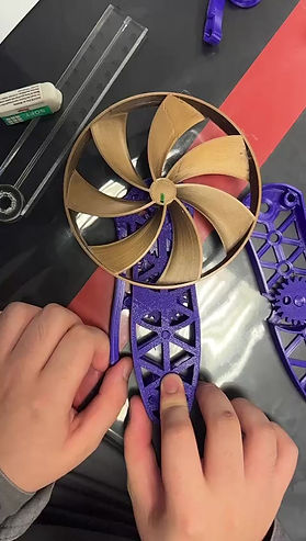

Initially, the fan had a 9T (follower), 9T/20T and 10T/20T (idlers - compound), and a 20T(driver). This allowed the fan to spin but in order to improve it, we needed a lower gear ratio to make the fan spin faster, displacing more air and improving cooling. Due to the space contraints of the fan handle, we could only make the compound gears have a smaller gear configuration of 20T-5T standard for all compound gears and the final follower gear to be 5T.
Initially, the gear ratio was as follows:
Gear ratio = 20/10 x 20/9 x 20/9 = 9.87
which means for every 1 revolution of the driver, the follower rotates roughly 10 times.
With the proposed improvement;
Gear ratio = 20/5 ^3 =64
this means that for every 1 rotation of the driver gear, the fan would have have spun 64 times, displacing more air and blowing more air onto the user.

Reflection
I've realized that although it is a simple invention, it has greatly improved the way we do things. For example, on a bicycle, we are able to go fast or go up a hill easily by varying the gear ratio to our liking. Gears are also used in vehicle transmissions that allow them to go fast from a standstill quickly and efficiently. Gears are also used in clocks to keep time. I think that with my basic to intermediate knowledge of gears, I am able to utilize these pieces of equipment to aid my journey in CPDD when designing products and prototypes.